


1. Introduction
NMOS transistors are divided into two types: enhancement-mode and depletion-mode. Their turn-on logic is completely different. Many engineers encounter abnormal heating, failure to turn on, and circuit leakage due to misunderstanding NMOS conduction conditions.
This article uses plain technical language without complex mathematical formulas, fully compatible with all website editors, no garbled characters after pasting.
2. Enhancement-Mode NMOS (E-NMOS)
Most commonly used in power electronics, switching circuits, motor drives
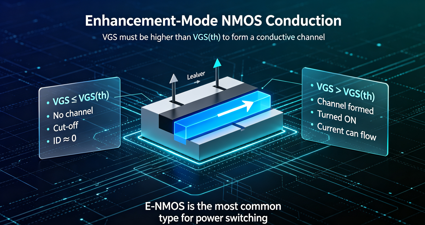
Feature: No built-in conductive channel inside the chip. The transistor is OFF by default at zero gate voltage.
2.1 Basic Conduction Condition
The gate-source voltage must be higher than the threshold voltage.
- Threshold voltage (VGS(th)) is a positive value for E-NMOS
- If gate voltage is lower than threshold voltage: NMOS keeps OFF, almost no drain current flows
- Effective driving rule: Set gate voltage 1V~3V higher than the threshold voltage for stable turn-on
2.2 Two Working States After Turn-On
After the NMOS is turned on, it has two operating regions determined by drain-source voltage:
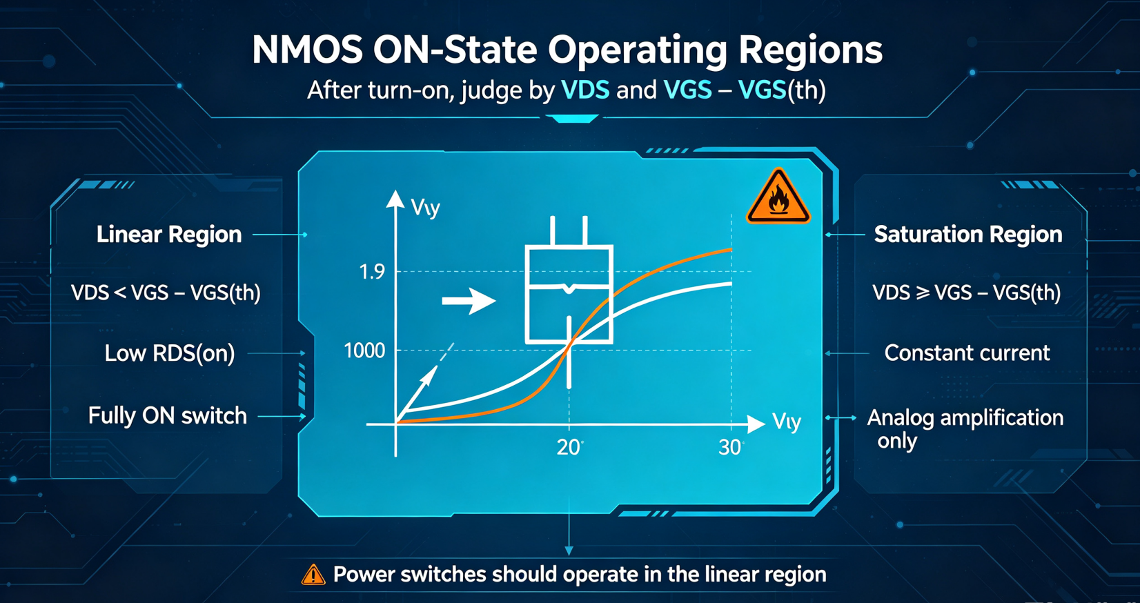
2.2.1 Linear Region (Fully ON, Recommended for Switches)
Condition: The drain-source voltage is much lower than the effective overdrive voltage.
- Extremely low on-resistance (RDS(on))
- Very low voltage drop and low power loss
- Application: Load switch, DC-DC converter, BLDC motor drive
2.2.2 Saturation Region (Constant Current, For Analog Only)
Condition: The drain-source voltage is greater than or equal to the effective overdrive voltage.
- Drain current is fixed and will not increase with voltage
- High internal impedance, serious heat generation
- Application: Signal amplification, constant current source, current limiting circuit
- Do not use for power switching, easy to burn out the MOSFET
3. Depletion-Mode NMOS (D-NMOS)
Special type, mainly for RF and analog circuits, rarely for power switches
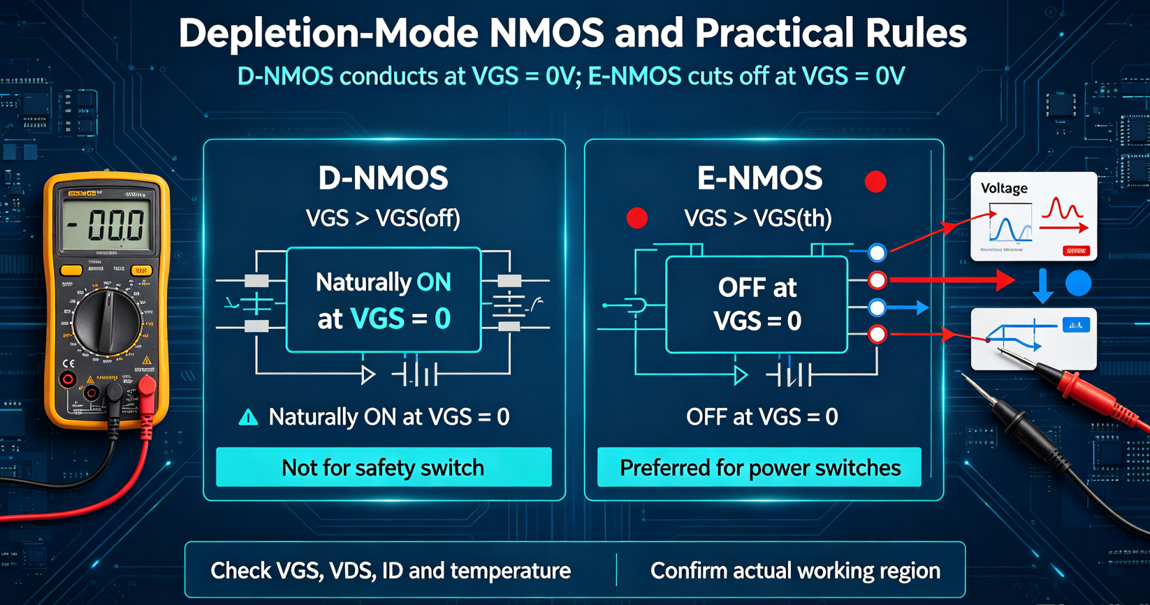
Feature: Built-in permanent conductive channel inside the chip. The transistor is ON by default at zero gate voltage.
3.1 Basic Conduction & Cut-off Rule
- Default state (0V gate voltage): Fully ON
- Always ON when gate voltage is positive or zero
- Turn OFF only when gate voltage drops below the negative pinch-off voltage (VGS(off))
3.2 Working Region Classification
Same as enhancement NMOS, divided into linear region (low resistance) and saturation region (constant current) according to drain-source voltage.
Typical application: RF low-noise amplifier, high-impedance analog load
4. Engineering Practical Rules (No Garbled Characters)
4.1 Enhancement NMOS Practical Tips
- Gate floating or connected to GND = fully OFF (safe for power systems)
- 3.3V MCU driving: select low threshold NMOS to ensure full turn-on
- 10V standard driving: best for low RDS(on) performance
- Keep the MOSFET in the linear region during switching operation to avoid overheating
4.2 Depletion NMOS Practical Tips
- Cannot be used as a safety power switch, always ON at zero gate voltage
- Requires negative voltage power supply to turn off the device
- Not recommended for battery management and high-current switching scenarios
5. Core Summary
- Enhancement NMOS: OFF at 0V, turn ON when gate voltage exceeds threshold voltage
- Depletion NMOS: ON at 0V, only turn OFF with negative gate bias
- Power design must use linear region to reduce heat loss
- Saturation region is only limited to analog signal and constant current circuits


-

Did you know about the evolution of MOSFET?
-

Analysis of the reasons for the ineffectiveness...
-

Production method of high power MOSFET driving ...
-

BJT vs MOSFET: Making the Right Choice for Your...
-

Difference Between Unipolar SPWM & Bipolar...
-

What can I do to fix my MOSFET that is heating ...
-

Understanding the function and structure of MOS...
-

Detailed explanation of the working principle d...
-

Understanding MOSFET Saturation: Key Operating ...
-

FET DFN2X2 package single P-channel 20V-40V mod...
-

Conduction Conditions of NMOS Transistors
-
MOSFET Package Switching Tube Selection and Cir...
-

Mastering FET Connections for Seamless Circuit ...
-

How to Evaluate MOSFET Performance Parameters D...
-

Fast Switching MOSFETs: The Complete Guide to N...
-

Analyzing Enhancement and Depletion MOSFETs


