


Core formula: Ipeak = Qg / trQg: total gate charge from datasheet, unit nC
tr: target rise time (VDS fall time), unit ns
The Miller plateau produces the highest peak current. This phase mainly consumes Qgd (Miller charge) and dominates switching loss and EMI performance.
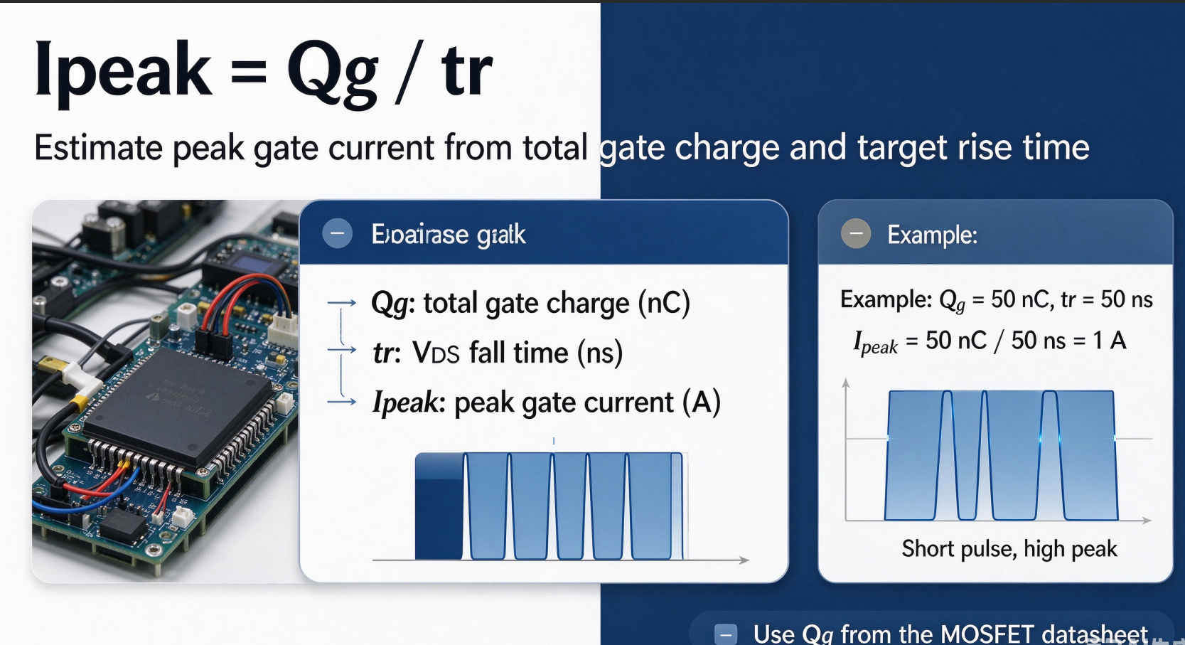
Engineering Reference Range (for BLDC motor controllers & lithium battery protection power MOSFETs)
-
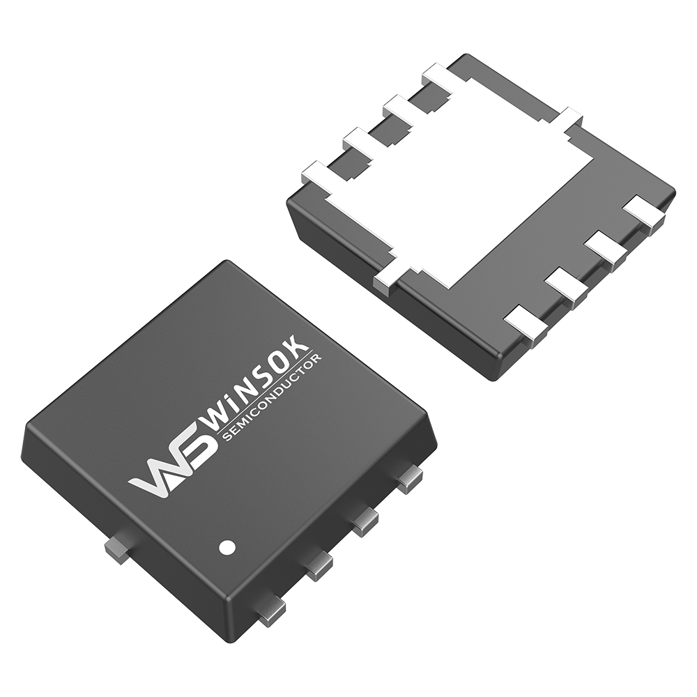
Small MOSFETs (SOT23, TO252, Qg ≈ 5~20 nC)
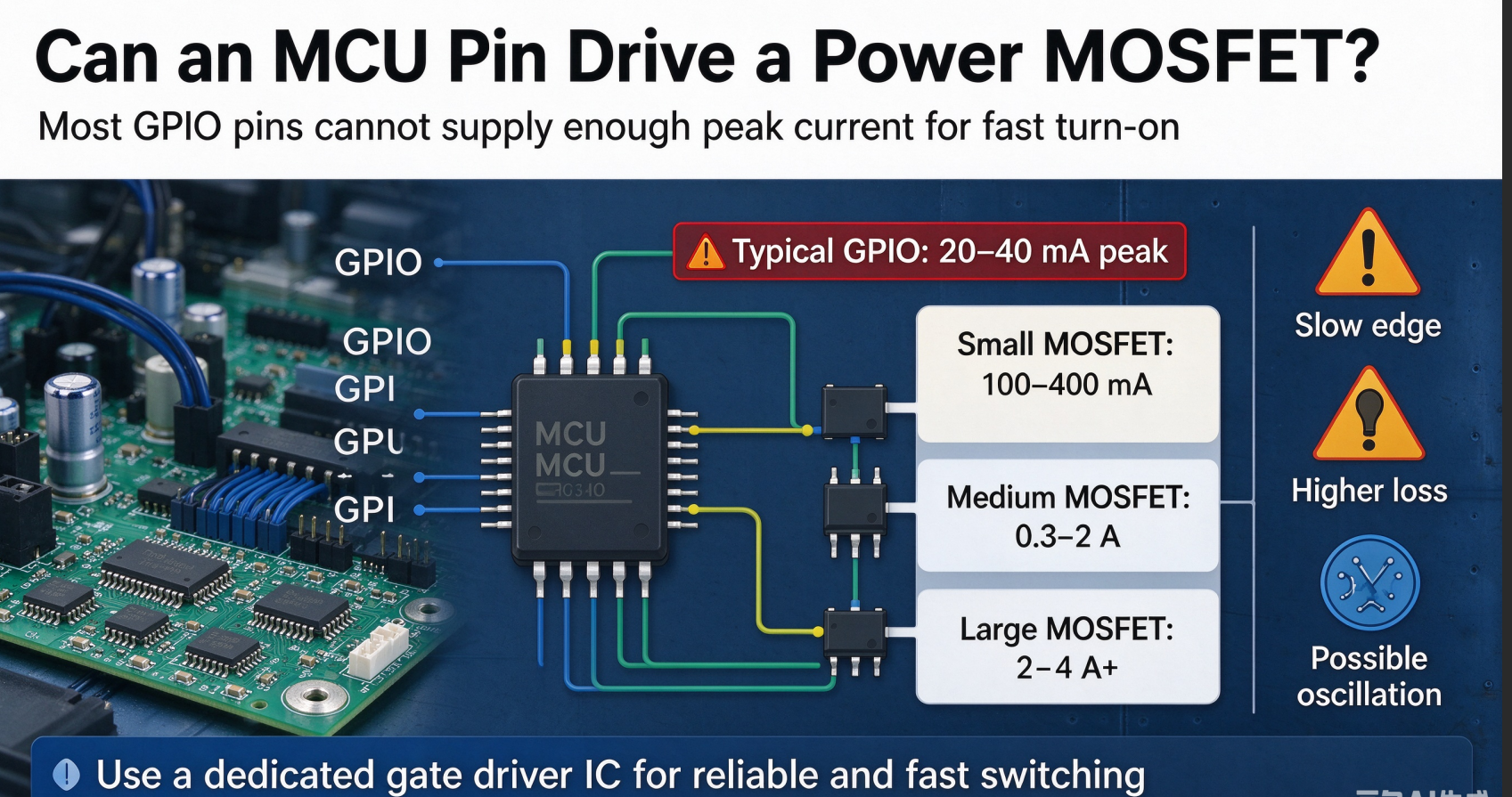
Target rise time 50~100 ns → peak current 100 mA ~ 400 mA. Direct driving by simple logic IO is barely functional but not recommended. Insufficient driving capability creates slow switching edges and higher heat generation.
-
Medium-power MOSFETs (TO220, DPAK, Qg ≈ 30~100 nC, widely used for motor bridge arms)
Target rise time 50~100 ns → peak current 0.3 A ~ 2 A. This is the typical range for BLDC controllers. Gate driver ICs with 1 A ~ 2 A peak drive current are commonly selected. An external gate resistor Rg is added to limit peak current and suppress oscillation.
-
High-current low-Rds(on) MOSFETs (large packages, big die size, Qg >100 nC)
For fast turn-on, peak current can reach 2 A ~ 4 A or higher. This category requires dedicated high-current gate drivers. Never drive directly from MCU pins.
The gate resistor Rg is used to limit this instantaneous peak current. Larger Rg reduces peak current and slows the switching edge, lowering EMI at the cost of higher switching loss. Smaller Rg gives faster turn-on and lower switching loss, but may trigger VDS ringing and EMI violation. This is the classic engineering trade-off tied to the Miller effect.
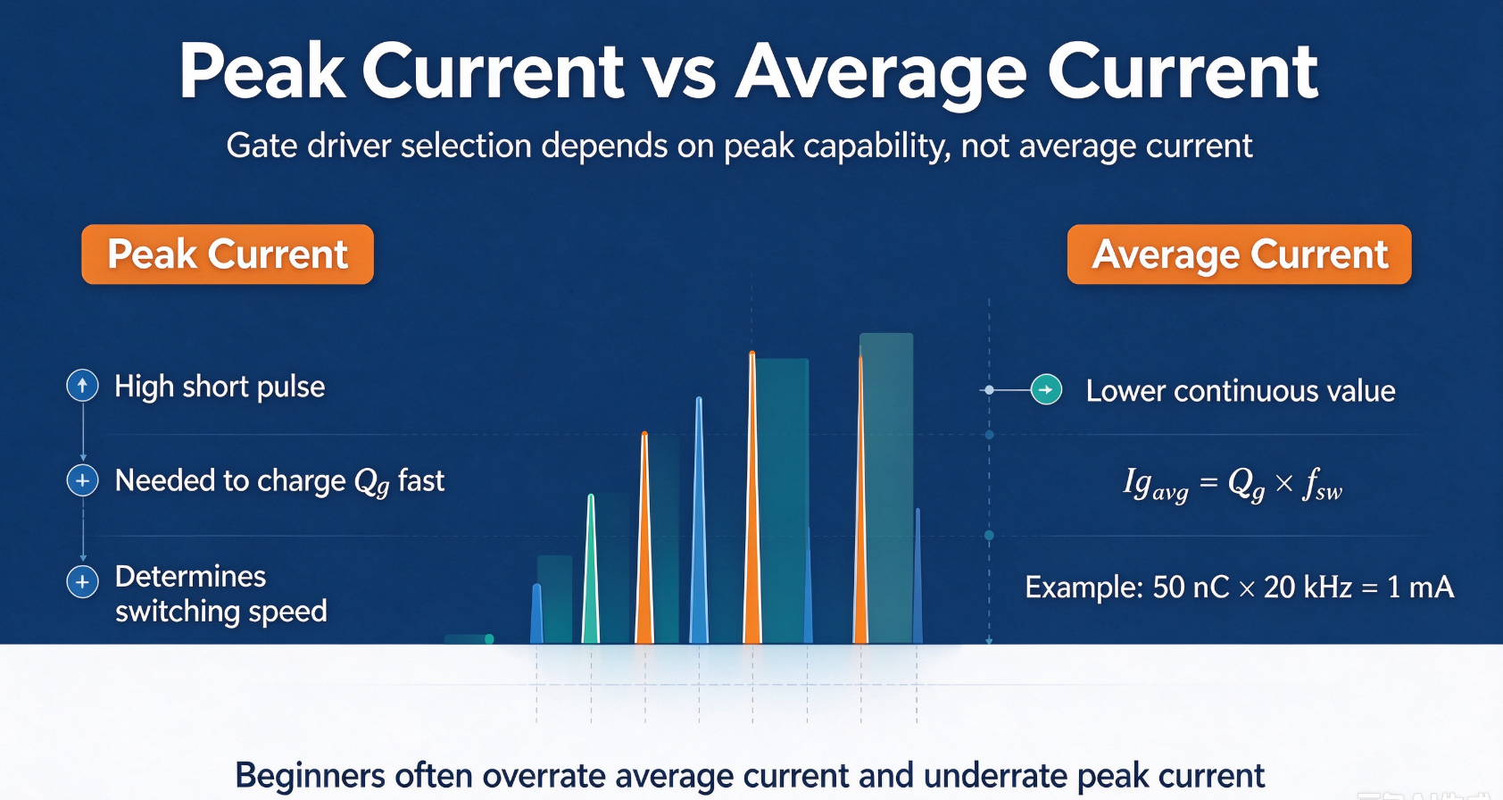
Average Gate Drive Current (Do not confuse with peak current)
Ig_avg = 50 nC × 20 kHz = 1 mA.
The average current represents total charge transferred per second and is usually small. When selecting gate driver ICs, always check peak drive capability, not average current. This is a frequent pitfall for beginners.
Simple Selection Guidelines
- Low-speed applications without high efficiency requirements: reduce peak drive current and accept slower switching.
- High-frequency, high-current BLDC motor controllers: reserve 1.5~2 times design margin for peak drive current.
- MCU IO pins typically only source/sink 20~40 mA. They can hardly drive power MOSFETs directly, even for MOSFETs with moderate Qg, once switching speed matters.
Summary


-

MOSFET Solid State Relays: Revolutionizing Mode...
-

High Voltage Gate Drivers: Advancing Power Elec...
-
MOSFET small current heating causes and measures
-

CMS32L051SS24 MCU Cmsemicon® Package SSOP24 Bat...
-
MOSFETs in Electric Vehicle Controllers
-

BJT vs MOSFET: Making the Right Choice for Your...
-

Impacts Caused by Damaged Anti-Reverse MOSFET
-

Using a MOSFET as a Switch: Complete Implementa...
-

MOSFET Failure Analysis: Understanding, Prevent...
-

Testing MOSFETs on PCBs: Field Testing Methods ...
-
How can I tell the difference between a Mosfets...
-
The connection between MOSFETs and Field Effect...
-

MOSFET Anti-Reverse Circuit
-
The difference between N-channel MOSFET and P-c...
-

The importance of power MOSFET in motherboard d...
-

How to Use a MOSFET: Complete Guide for Beginne...


