
1. Introduction
Many engineers only refer to MOSFET datasheet parameters for device selection, but do not know how to use real-time electrical parameters to judge the actual working state of the MOSFET in the circuit. Correct state judgment helps troubleshoot heating, abnormal switching, breakdown and circuit instability issues quickly.
This article summarizes a fully practical judgment method based on core parameters: VGS, VDS, ID, RDS(on).
2. Three Basic Working States of MOSFET
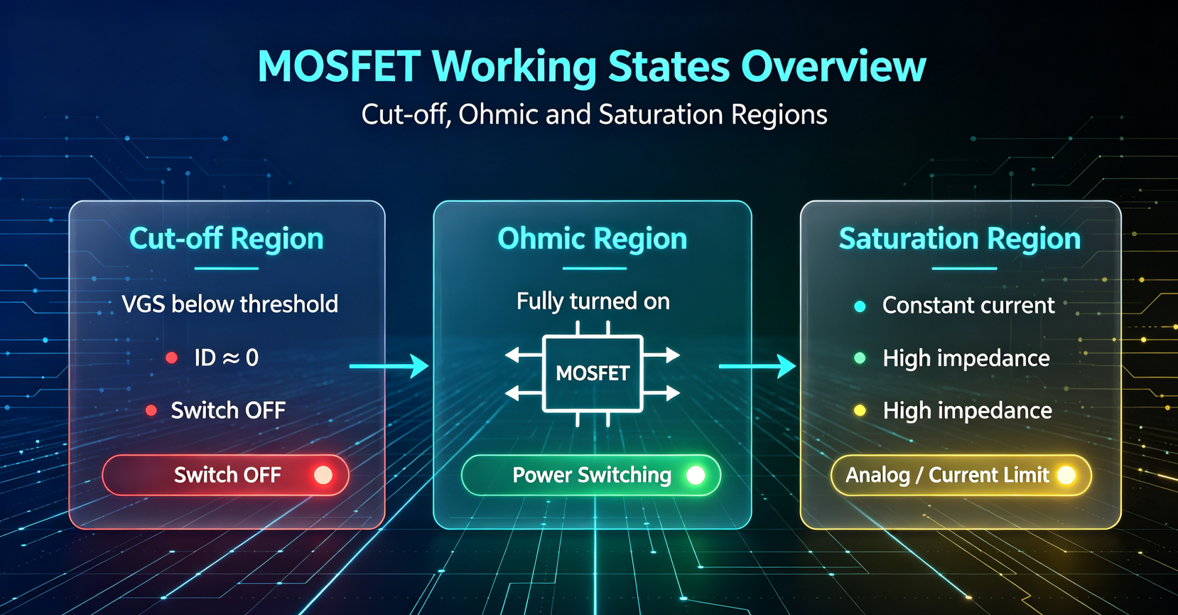
All MOSFETs (Enhancement / Depletion, N-channel / P-channel) have only three working states:
- • Cut-off Region (OFF): No current conduction, used for switch-off state
- • Ohmic Region (Linear / ON): Fully turned on, low resistance conduction, main state for power switches
- • Saturation Region (Active): Constant current output, mainly used for analog amplification and current limiting
3. Judgment Rules for N-Channel MOSFET (Most Common)
3.1 Enhancement Mode MOSFET (E-MOS)
Core reference parameter: VGS(th) — Threshold Voltage
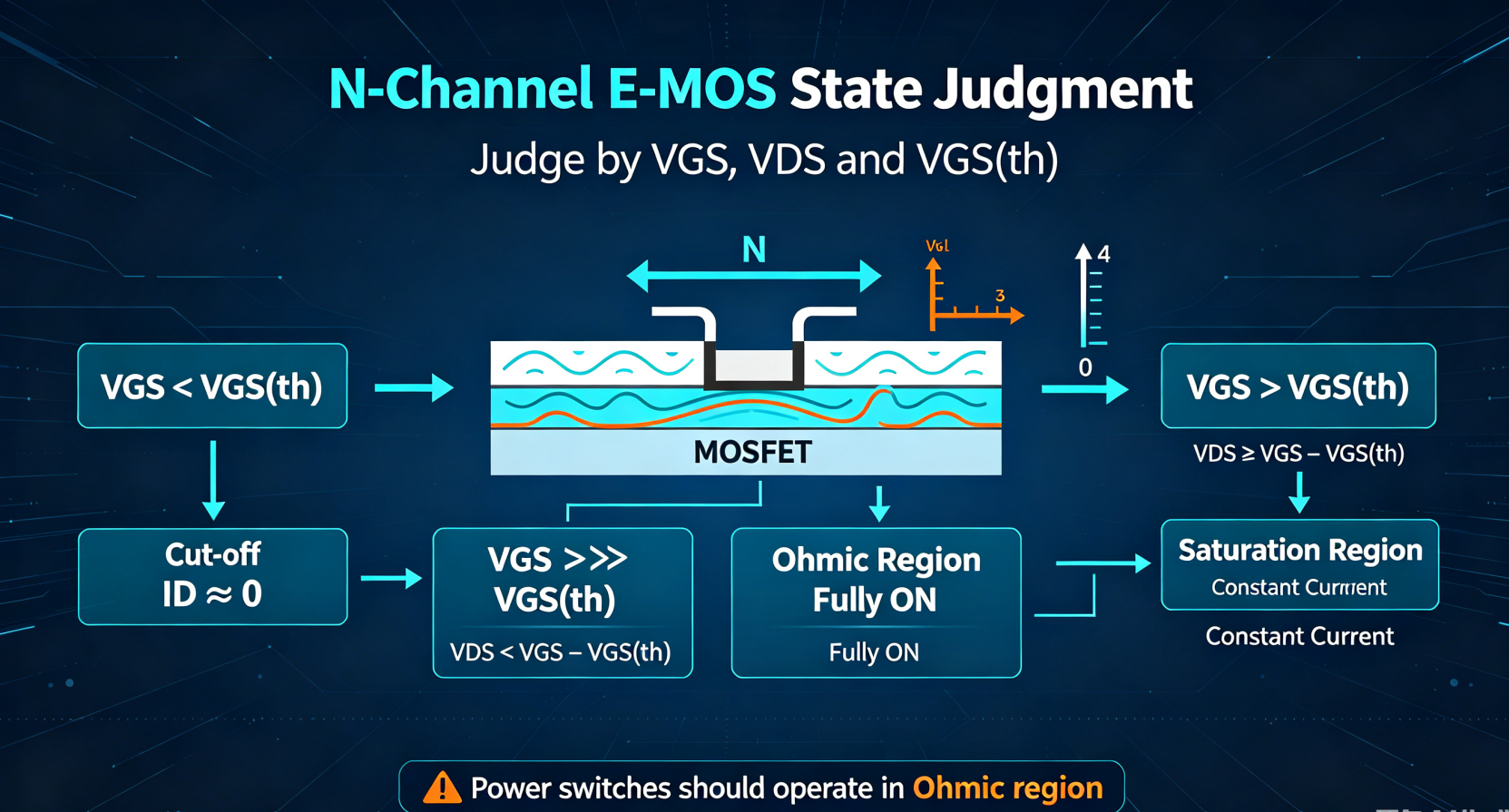
State 1: Cut-off (OFF)
Judgment condition: VGS < VGS(th)
- No conductive channel formed between drain and source
- Drain current ID ≈ 0
- VDS is close to the input power supply voltage
Typical scenario: Gate floating, MCU low-level turn-off
State 2: Ohmic Region (Fully ON)
Judgment conditions:
1. VGS ≫ VGS(th) (fully driven, such as VGS=5V/10V)
2. VDS < VGS − VGS(th)
- Internal channel resistance = RDS(on) (minimum value)
- VDS voltage drop is very small, low heat generation
- Used for power switching, motor drive, DC-DC circuit
State 3: Saturation Region (Constant Current)
Judgment conditions:
1. VGS > VGS(th) (channel opened)
2. VDS ≥ VGS − VGS(th)
- ID no longer increases with VDS, forming constant current output
- Large internal impedance, severe heat generation
- Used for signal amplification, current source, current limiting protection
3.2 Depletion Mode MOSFET (D-MOS)
Core reference parameter: VGS(off) — Pinch-off Voltage (negative value)
State 1: Cut-off (OFF)
Judgment condition: VGS < VGS(off) (more negative than pinch-off voltage)
The native channel is completely depleted, ID=0
State 2: Ohmic Region (ON)
Judgment condition: VGS(off) < VGS ≤ 0V / positive VGS
Conductive channel exists, low resistance conduction
State 3: Saturation Region
Same voltage logic as enhancement mode, used for RF amplification and analog circuits
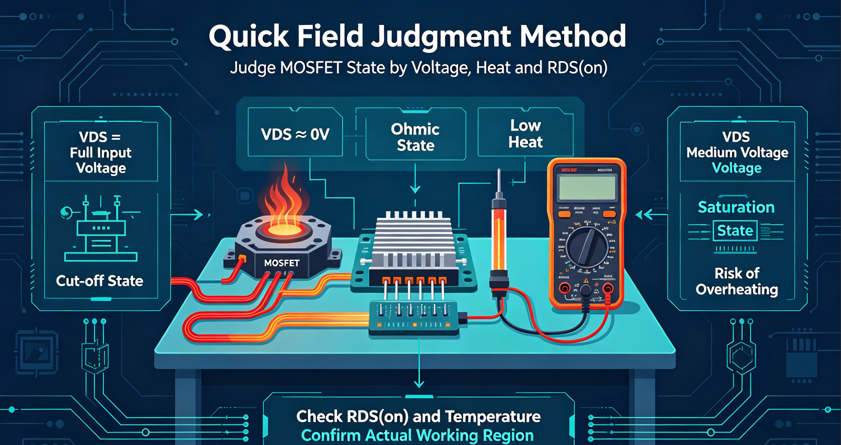
4. Quick Field Judgment Method (For Engineer Debugging)
You can directly judge the working state by measuring voltage with a multimeter without calculating formulas.
4.1 Judge by VGS
- VGS = 0V → E-MOS: OFF; D-MOS: ON
- VGS = 3~10V → E-MOS fully turned on (Ohmic state)
- VGS is between threshold and driving voltage → easy to enter saturation & overheat
4.2 Judge by VDS (Most Intuitive)
- VDS = Full input voltage → MOS is Cut-off
- VDS ≈ 0V (very small drop) → MOS is Fully ON (Ohmic)
- VDS is medium voltage (not 0, not full voltage) → MOS is in Saturation (dangerous heating state)
4.3 Judge by RDS(on) & Temperature
- Measured RDS(on) matches datasheet → normal fully ON state
- MOS is hot while VDS is not zero → working in saturation region
- No heat, no current → cut-off state
5. Common Misjudgment & Engineering Risks
- Misunderstanding 1: As long as VGS is high, the MOS is fully ON
Fact: If VDS is too large, the MOS still stays in saturation and overheats - Misunderstanding 2: Heating means poor MOS quality
Fact: Most heating is caused by the MOS staying in the saturation region for a long time - Misunderstanding 3: Depletion MOS can be used as power switch
Fact: VGS=0 is ON, it cannot fail-safe cut-off, not suitable for power switching
6. Summary
- Determine Cut-off / Ohmic / Saturation mainly by comparing VGS with VGS(th) and VDS with VGS−VGS(th)
- For field debugging, use VDS voltage value to judge state fastest
- Power circuits must keep MOS in Ohmic region to avoid heating and breakdown
- Saturation region is only suitable for analog current limiting and signal amplificatio


-

Mastering Darlington Transistors: From Basic As...
-

Working with MOSFETs: Essential Knowledge for E...
-

D-MOSFET Construction and Working Mechanism: Po...
-

Understanding E-MOSFET: The Building Block of M...
-

TFET vs MOSFET: Understanding the Future of Tra...
-

Fast Switching MOSFETs: The Complete Guide to N...
-

MOSFET Gate, Drain, and Source: Core Principles...
-

Understanding MOSFET Saturation: Key Operating ...
-

How to Measure MOSFET Power Breakdown: A Compre...
-

Original spot CMS79F726 package SOP20 touch but...
-

Four Types of MOSFETs
-

MOSFET Variable Resistors: Engineering Solution...
-

Analysis of important causes of MOSFET heat gen...
-

Lithium battery charging is easy to damage, WIN...
-

Understanding MOSFET Switching Speed for Optima...
-

Understanding MOSFET’s Capacitive Propert...


