


1. Preliminary Visual Inspection
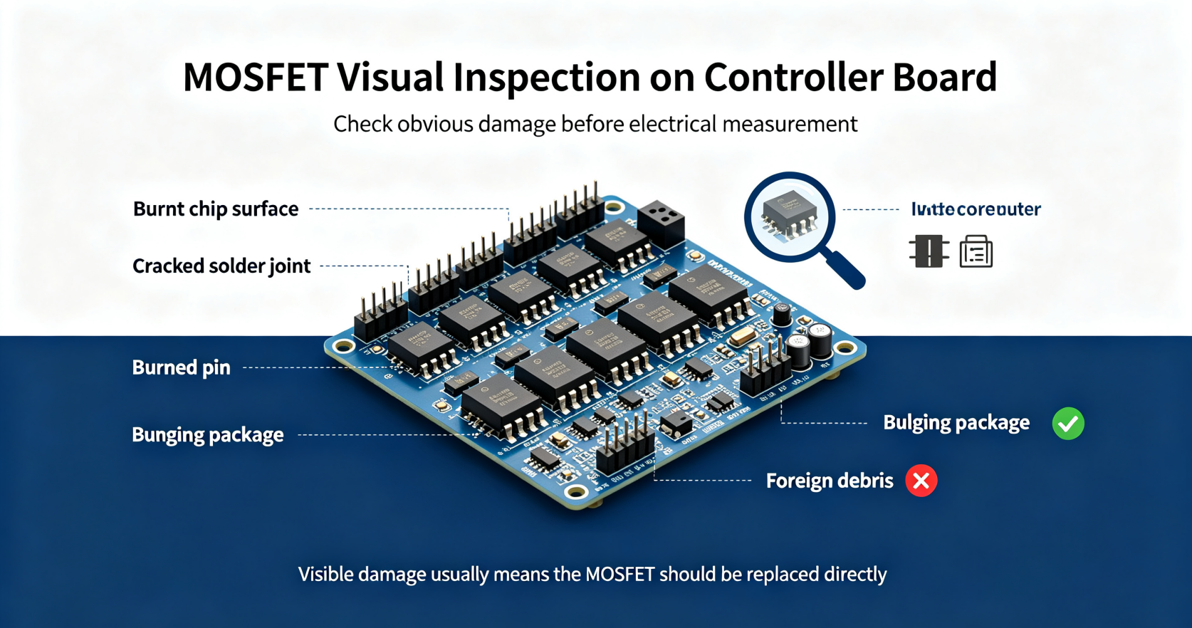
Check the appearance of the MOS tube first. Observe whether the chip surface is burnt, the pins are burned open‑circuit, the solder joints are cracked or the plastic package bulges. If obvious damage is found, the device is directly judged defective without further electrical measurement.
2. Diode Mode Test with a Digital Multimeter
Switch the multimeter to the diode test gear. For a normal power MOSFET, there is a body diode between drain and source. For NMOS, the positive lead touches the source pin and the negative lead touches the drain pin, the multimeter will show a forward voltage value around 0.4‑0.7 V. Reversing the probes will display an open‑circuit state. If it conducts in both directions or shows no conduction at all, the MOSFET is broken down or open‑circuit.
3. Gate Insulation Resistance Measurement
Set the multimeter to high‑resistance mode. Measure the resistance between the gate pin and drain, gate and source. A good MOSFET shows infinite resistance. If a fixed resistance value appears, the gate oxide layer has broken down and the part fails. The gate cannot be driven normally after insulation damage.
4. Manual Trigger Test for Switching Performance
Short the gate pin to the source pin first to release residual electric charge. Then briefly touch the gate with the positive probe of a 3‑5 V power supply. After charging the gate, measure the resistance between drain and source. The resistance will drop to a very low level when the tube turns on. Short gate and source again to discharge, and the D‑S resistance returns to high impedance. If the on‑off state cannot be switched, the MOSFET loses its switching function.

5. In‑circuit Online Measurement
You do not need to desolder the MOSFET from the controller board. Compare the diode voltage drop of each bridge arm MOS tube one by one. If one channel has a completely different reading from the others, this tube is suspected of failure. Note that peripheral resistors or parallel devices will interfere with the reading, so online testing is only used for preliminary screening.
6. Desoldered Full‑parameter Verification
Remove the MOSFET from the PCB for independent testing. Use a transistor tester to measure threshold voltage Vgs(th), on‑resistance Rds(on) and breakdown voltage Vdss. When the actual parameter deviates greatly from the datasheet specification, the component will cause abnormal operation of the controller even if the simple diode test passes.
7. Power‑on Dynamic Test
Assemble the qualified MOSFET back to the controller. Run the controller under no‑load and light‑load conditions, and detect the temperature rise of each power tube. A severely overheating MOSFET indicates partial damage, high conduction loss or unstable switching characteristics, which will lead to controller failure during actual operation.
Summary
Visual inspection and multimeter diode measurement are the fastest field maintenance methods. Gate charge trigger testing can verify basic switching capability. For accurate judgment, off‑line parameter testing and real‑load power‑on verification are reliable ways to confirm whether the controller MOSFET is good or damaged.


-

What is the difference between MOSFET and IGBT?...
-

WINSOK|China e-Hotspot Solution Innovation Summ...
-

Power MOSFET Package Types Guide
-
Explanation of each parameter of power MOSFETs
-

MOSFET conduction characteristics
-
What are the functions of MOSFET?
-

New MOSFET Sourcing Choice: WINSOK Domestic Sub...
-

How to Select Gate Resistor for Anti-Reverse MO...
-

What Happens If You Use Too‑Large Gate Resistor...
-
MOSFET original basic knowledge and application
-

What is MOSFET in Electronics: Definition, Work...
-

A Comprehensive Guide about What is VGS in MOSFET
-

MOSFET Gate Driver ICs: Maximizing Power Effici...
-

Do You Know About MOSFET Circuits?
-

MOSFET Motor Control: Advanced Solutions for Mo...
-

MOSFET Operating Characteristics


