
1. Core Definition (Conduction State at Zero Gate-Source Voltage)
1.1 Enhancement-Mode MOSFET (E-MOSFET)
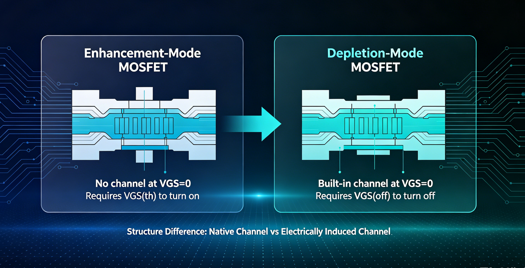
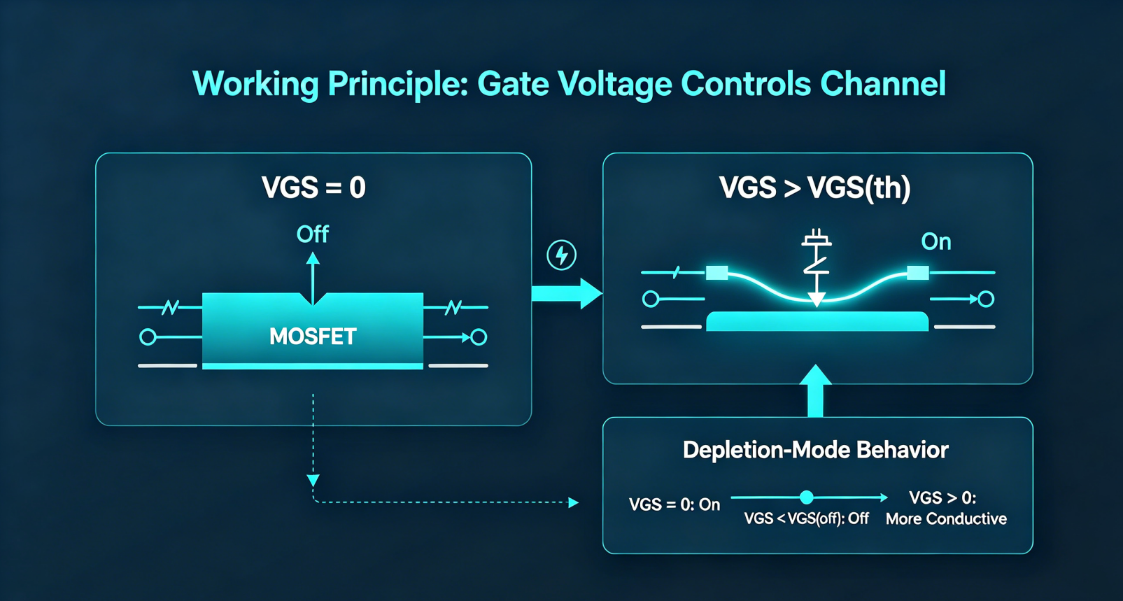
When VGS = 0, no conductive channel exists, and the device is cut off with nearly zero drain current.
A gate-source voltage exceeding the threshold voltage VGS(th) must be applied to form a conductive channel and turn the device on.
- N-channel enhancement MOSFET: Turns on when VGS is higher than positive threshold voltage
- P-channel enhancement MOSFET: Turns on when VGS is lower than negative threshold voltage
1.2 Depletion-Mode MOSFET (D-MOSFET)
Ions are implanted into the channel during manufacturing. A permanent conductive channel already exists at VGS = 0, so the device conducts naturally without gate bias.
The channel is depleted by applying reverse gate voltage to switch the device off; its key parameter is pinch-off voltage VGS(off).
- N-channel depletion MOSFET: Conducts at VGS=0; cuts off only when VGS drops below negative pinch-off voltage
- P-channel depletion MOSFET: Conducts at VGS=0; cuts off only when VGS rises above positive pinch-off voltage
2. Key Parameter Comparison Table
| Comparison Item | Enhancement-Mode MOSFET (E-MOS) | Depletion-Mode MOSFET (D-MOS) |
|---|---|---|
| Status at VGS=0 | No channel, fully cut off | Built-in channel, fully conductive |
| Characteristic Voltage | Threshold voltage VGS(th) | Pinch-off voltage VGS(off) (negative for N-channel, positive for P-channel) |
| Operating Gate Voltage Range | Only single-polarity voltage enables conduction (positive bias for N-channel, negative bias for P-channel) | Supports positive, zero and negative gate bias, ultra-wide operating flexibility |
| Conduction Mechanism | Electric field enhances carriers to create a new channel | Pre-fabricated channel; reverse electric field depletes carriers to shut down conduction |
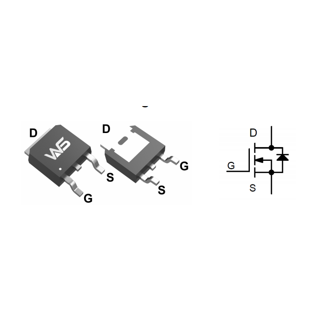
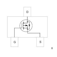
| Circuit Symbol | Dotted line between source and drain (no native channel) | Solid line between source and drain (native conductive channel) |
| Common Part Numbers | 2N7002, IRF3205, silicon power MOSFETs, internal switches in MCUs | Small-signal devices: JFET, 3DJ6, 2SK series RF transistors |
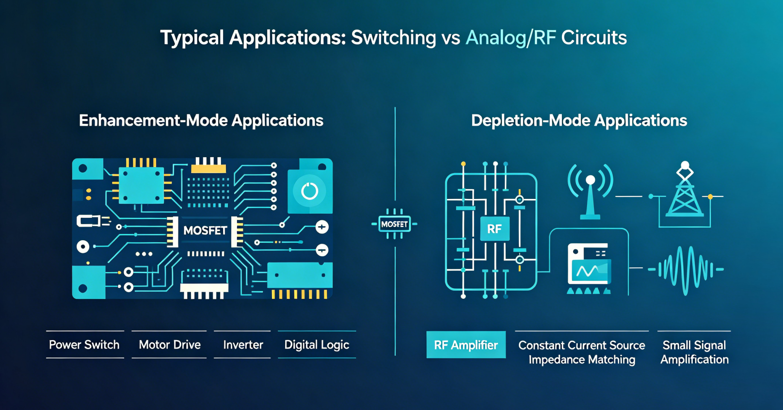
| Typical Applications | Power switches, motor drivers, digital logic, inverters, BLDC motor drives | RF amplifiers, constant current sources, impedance matching, small-signal amplification |
3. Practical Working Example of N-Channel MOSFETs (Most Widely Used)
N-Channel Enhancement-Mode MOSFET
VGS(th) = +2V
- VGS = 0V: Cut off, drain current ID ≈ 0
- VGS = 5V: Fully turned on, large drain current flows
N-Channel Depletion-Mode MOSFET
VGS(off) = -4V
- VGS = 0V: Fully conductive, stable drain current output
- VGS = -5V: Channel depleted, device cut off
- VGS = +3V: Channel widens further, drain current increases significantly
4. Circuit & Application Differences
4.1 Enhancement-Mode MOSFET (Industry Standard Choice)
- Simple control: Automatically cuts off when gate is floating or zero-biased, high safety margin
- Straightforward driving circuit, no negative voltage supply required
- Dominant solution for power MOSFETs, switching power supplies, motor drives and digital chips
4.2 Depletion-Mode MOSFET (For Analog & RF Circuits Only)
- Operable at VGS=0 without extra bias circuitry
- Ideal for constant-current loads, high-frequency amplifiers and RF low-noise amplifiers
- Drawback: Remains conductive with zero gate bias; unsuitable for high-power switching circuits due to safety risks
5. Quick Identification via Schematic Symbols
- Enhancement-mode: Dotted channel line between source and drain
- Depletion-mode: Solid channel line between source and drain
6. One-Sentence Summary
- Enhancement-mode MOSFET: Non-conductive with zero gate bias; turns on only with applied gate voltage (mainstream switching device)
- Depletion-mode MOSFET: Conductive by default at zero gate bias; requires reverse gate voltage to turn off (specialized for analog & RF circuits)


-
What parameters should I pay attention to when ...
-

How to Use a MOSFET: Complete Guide for Beginne...
-

Best MOSFETs for Inverter Applications: Expert ...
-

The connection between MOSFETs and Field Effect...
-

How to Read & Describe MOSFET Specificatio...
-
How to choose MOSFET?
-

How Long Do MOSFETs Last? A Comprehensive Guide...
-

Important Steps on MOSFET Selection
-

How to Use N-Channel MOSFET: An Implementation ...
-

Parallel Theory of MOSFETs and Transistors
-

Causes and Prevention of MOSFET Failure
-
MOSFETs in Electric Vehicle Controllers
-

2N7002 LTspice Modeling and Simulation Guide
-
MOSFET small current heating causes and measures
-
MOSFET Package Switching Tube Selection and Cir...
-

What are the functions of MOSFET?


