


Introduction
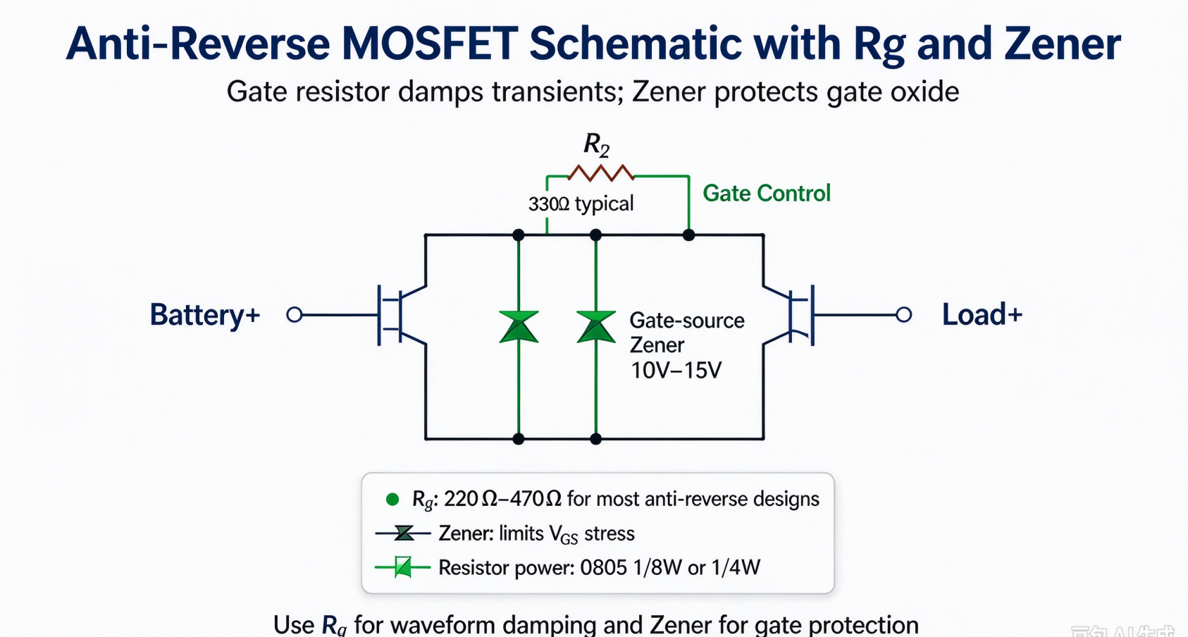
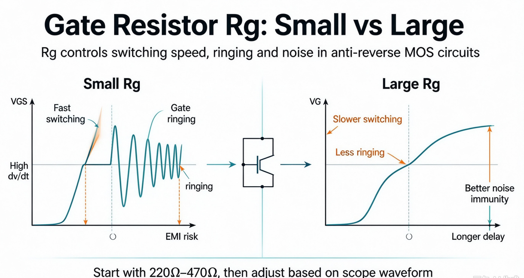
The gate resistor is a simple yet critical component in anti-reverse MOS circuits. It controls gate charging/discharging speed, suppresses oscillation, and prevents false turn-on. Too small a resistor causes gate ringing and EMI noise; too large slows down MOS switching and may trigger protection failure under fast reverse surge.
Core Working Principle
MOSFET gate is essentially a capacitor (Ciss). The gate resistor together with gate capacitance forms an RC network.
- Small Rg → fast charge/discharge → high dv/dt, risk of oscillation, EMI
- Large Rg → slow charge/discharge → longer turn-on / turn-off delay
Recommended Value Range for Anti-Reverse MOS
For most low-to-medium power anti-reverse MOS applications (battery input, BLDC controller, 12~48V DC):
100Ω ~ 1kΩ is the common starting range
- 100Ω ~ 330Ω: Preferred for high-current anti-reverse circuit. Fast response to block reverse current; good for handling sudden reverse surge. Use when PCB layout is clean and short gate trace.
- 470Ω ~ 1kΩ: For noisy environment, long gate wiring. Dampen gate oscillation, avoid false turn-on caused by noise coupling. Tradeoff: slightly slower reaction.
❗ Avoid less than 50Ω: easy to trigger high-frequency oscillation on gate pin, damage MOS.❗ Avoid above 2kΩ: switching delay becomes too big. When reverse voltage comes, MOS may not turn off fast enough and fail anti-reverse protection.
Key Selection Rules
-
N-channel anti-reverse MOS (high-side)
Gate drive voltage is relative to source pin, source follows battery positive. Usually use charge pump or bootstrap supply. Start with 220Ω~470Ω.
-
P-channel anti-reverse MOS (high-side battery input)
Most common anti-reverse topology. Gate signal swing between battery+ and GND. Start with 330Ω.
-
Power rating of gate resistor
Gate current is only transient pulse current, average power is tiny. 0805 package 1/8W or 1/4W resistor is sufficient for nearly all anti-reverse MOS designs. No need high-power resistor.
Debug Tips
- Measure gate waveform with oscilloscope. If obvious ringing / overshoot appears, increase Rg.
- If reverse protection test fails (MOS still damaged under reverse polarity), reduce Rg to speed up turn-off response.
- Add a gate-source Zener diode (10V~15V) in parallel for extra protection, prevent gate oxide breakdown from voltage spike.
Summary
For anti-reverse MOSFET, 220Ω ~ 470Ω is the default recommended value. Start from 330Ω for prototype. Adjust up or down based on oscilloscope waveform and reverse surge test. Gate resistor is not for adjusting steady-state current; its main job is waveform damping and switching speed tuning.


-

Do you know the three poles of MOSFET?
-

Wiring a MOSFET for Your Nerf Blaster: Professi...
-

Gate capacitance, on-resistance and other param...
-
About the working principle of power MOSFET
-

Understanding MOSFET Switching Speed for Optima...
-

High Side and Low Side Drivers: Powering Modern...
-

What do the three pins G, S, and D of the packa...
-

Power MOSFET Construction: Advanced Technology ...
-

Causes and Prevention of MOSFET Failure
-

Special Circuit Design for Power Amplifiers Usi...
-
Enabling High Power Applications: Winsok Mosfet...
-

EV dashboards are prone to break down, maybe it...
-

Mastering MOSFET as a Switch: Complete Implemen...
-

Mastering FET Connections for Seamless Circuit ...
-

Why the Absolute‑Value of PMOS Threshold‑Voltag...
-

How to determine whether a MOSFET is good or bad?


