


1. Basic Definition
SPWM (Sinusoidal Pulse Width Modulation) is widely used for BLDC sine drive, single-phase / three-phase inverters, UPS and power converters. According to the level of output voltage during switching, it is divided into unipolar SPWM and bipolar SPWM.
2. Core Working Principle
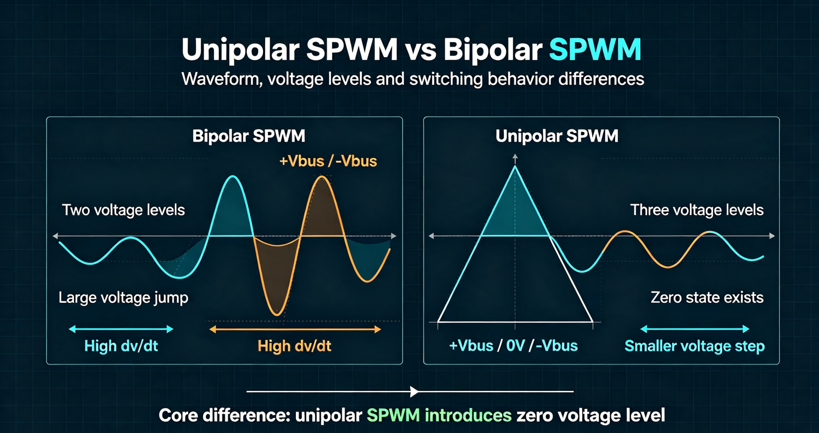
Bipolar SPWM
The carrier triangular wave swings between +Vcc and -Vcc.
- Reference sine wave compares with triangle wave
- The output terminal only has two states: +DC bus voltage / -DC bus voltage
- No zero voltage level during operation
Unipolar SPWM
Triangular carrier fluctuates between 0 ~ Vcc. Each bridge arm operates independently:
- Upper arm: switch according to sine positive half cycle
- Lower arm: switch according to sine negative half cycle Output contains three levels: +Vbus / 0V / -Vbus
3. Key Differences Comparison Table
| Item | Bipolar SPWM | Unipolar SPWM |
|---|---|---|
| Output voltage levels | 2 levels (+Vbus, -Vbus) | 3 levels (+Vbus, 0, -Vbus) |
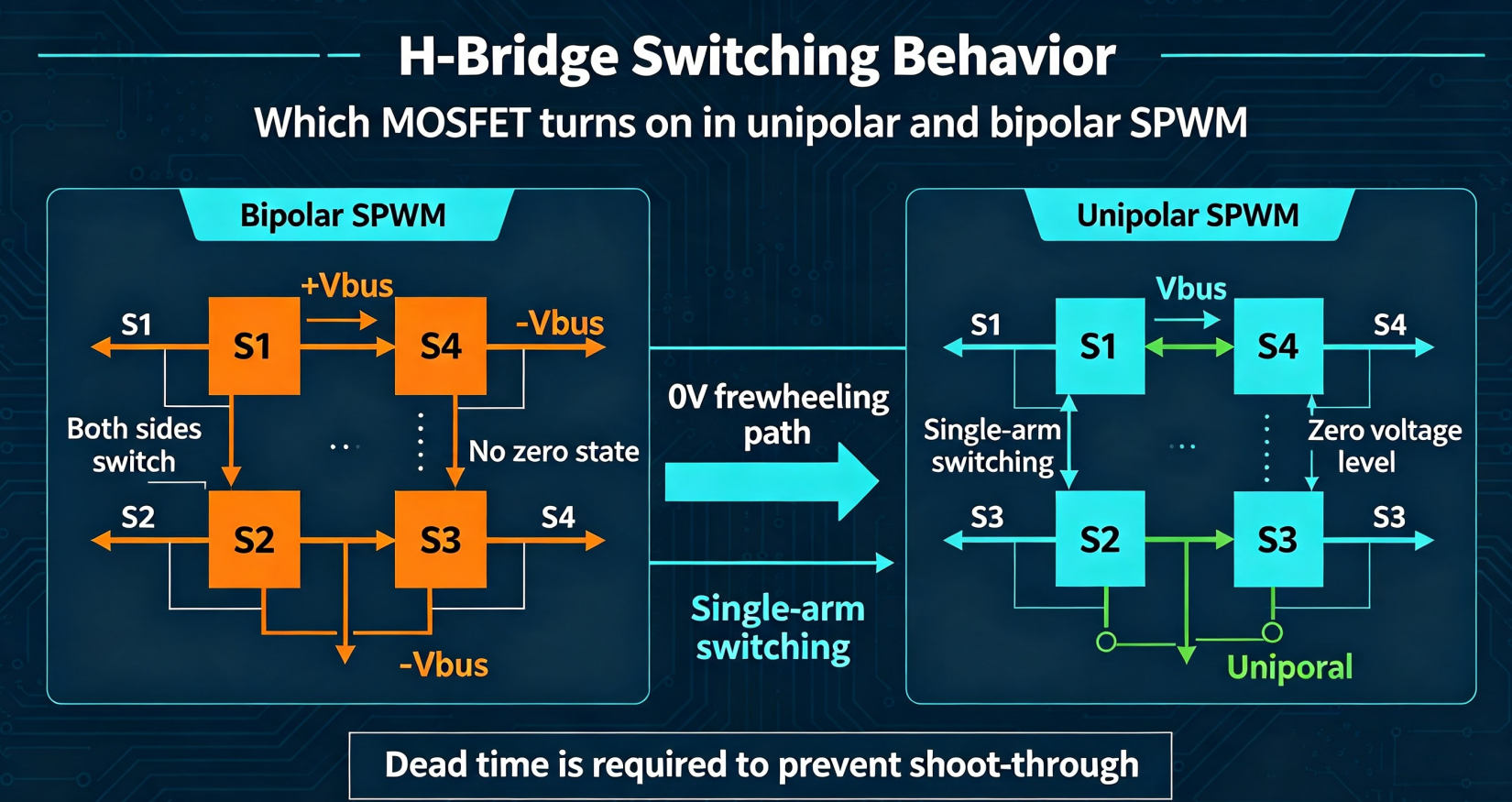
| Switching action | Both upper & lower tubes of H-bridge switch simultaneously | Only one side switches at any moment, opposite arm keeps OFF |
| Voltage swing amplitude | Full DC bus voltage jump (+Vbus ↔ -Vbus) | Voltage jumps between 0 and Vbus, smaller voltage step |
| dv/dt value | Large | Small |
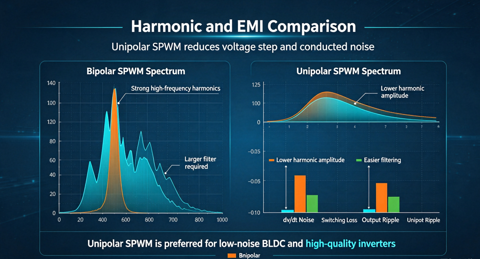
| EMI noise | Higher | Lower |
| Harmonic distribution | Main harmonic near 2×carrier frequency | Main harmonic near carrier frequency; easier filter |
| Filter requirement | Larger inductor / capacitor needed | Smaller filter parameters, lower loss |
| Loss characteristic | Higher switching loss | Lower switching loss |
| MCU algorithm difficulty | Simple, easy programming | More complex sampling & logic |
| Typical application | Low-cost small inverter, simple BLDC driver prototype | High-performance sine BLDC, audio amplifier, high-quality UPS |
4. Advantages & Disadvantages
Bipolar SPWM
✅ Advantages
- Algorithm simple, low requirement for MCU computing power
- Less logic code, stable debugging
- Suitable for low-cost control scheme
❌ Disadvantages
- Large voltage jump, high dv/dt, serious EMI interference
- High switching loss, MOS generates more heat
- Output current ripple bigger
Unipolar SPWM
✅ Advantages
- Small voltage transition amplitude, greatly suppress EMI
- Lower switching loss, reduce MOS heating
- Current ripple smaller, motor vibration & noise lower (critical for BLDC)
- Filter volume can be reduced
❌ Disadvantages
- Complicated program implementation
- Need higher performance MCU (such as China Micro MCU)
- Must strictly prevent upper and lower arms simultaneous shoot-through
5. Practical Engineering Suggestion for BLDC Motor
- Cost-sensitive low-end fan/pump: choose Bipolar SPWM
- High-end silent BLDC equipment (vacuum cleaner, garden tools, precision water pump): adopt Unipolar SPWM
- When using unipolar SPWM: match Winsok low Qg MOSFET to further cut switching loss
- No matter which mode, dead time setting is necessary to avoid H-bridge shoot-through damage MOS tubes
6. Summary
The most essential difference: Bipolar SPWM switches both bridge sides, voltage flips between positive and negative bus voltage. Unipolar SPWM only switches single arm, introduces zero voltage level, brings lower ripple, less EMI and less heating.


-

MOSFET Applications & Failure Analysis in ...
-

Master Guide: How to Read Power MOSFET Datashee...
-

Gate capacitance, on-resistance and other param...
-

How to Use a MOSFET: Complete Guide for Beginne...
-

High Side and Low Side Drivers: Powering Modern...
-

Operating Frequency Range of SiC MOSFET
-

PCM3360Q High-performance electronic components...
-

How to Use N-Channel MOSFET: An Implementation ...
-

What Are the Advantages of Power MOSFETs?
-

MOSFET vs FET: Why Modern Electronics Choose Me...
-

Ultimate Guide to MOSFET Power Amplifiers: Unde...
-

Basic Understanding of MOSFET
-

TFET vs MOSFET: Understanding the Future of Tra...
-

Mastering FET Connections for Seamless Circuit ...
-
The three main roles of MOSFETs
-

Leveraging Microcontroller Units for Cutting-Ed...


