


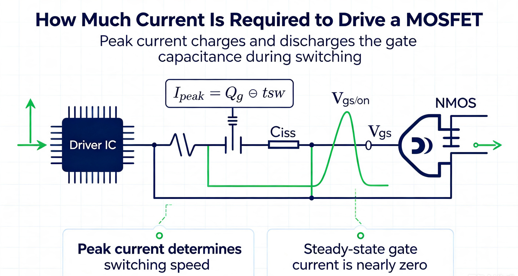
In fact, almost no current flows through the gate under steady-state conditions. However, instantaneous peak current is required to charge and discharge the gate capacitance during switching. The magnitude of driving current directly affects switching speed, heat generation, EMI performance and MOSFET reliability.
1. Basic Principle
Core formula:
Ipeak = Qg ÷ tsw
- Qg: Total gate charge (check datasheet, unit: nC)
- tsw: Target rise/fall switching time (unit: ns)
Key concept distinction
- Peak current: Pulse current at switching transients, which determines switching speed. This is the primary indicator for driver IC selection.
- Average driving current: Ig_avg = Qg × fsw, used to evaluate continuous heat generation of the driver IC.
2. Practical Engineering Reference (For BLDC Motors & Switching Power Supplies)
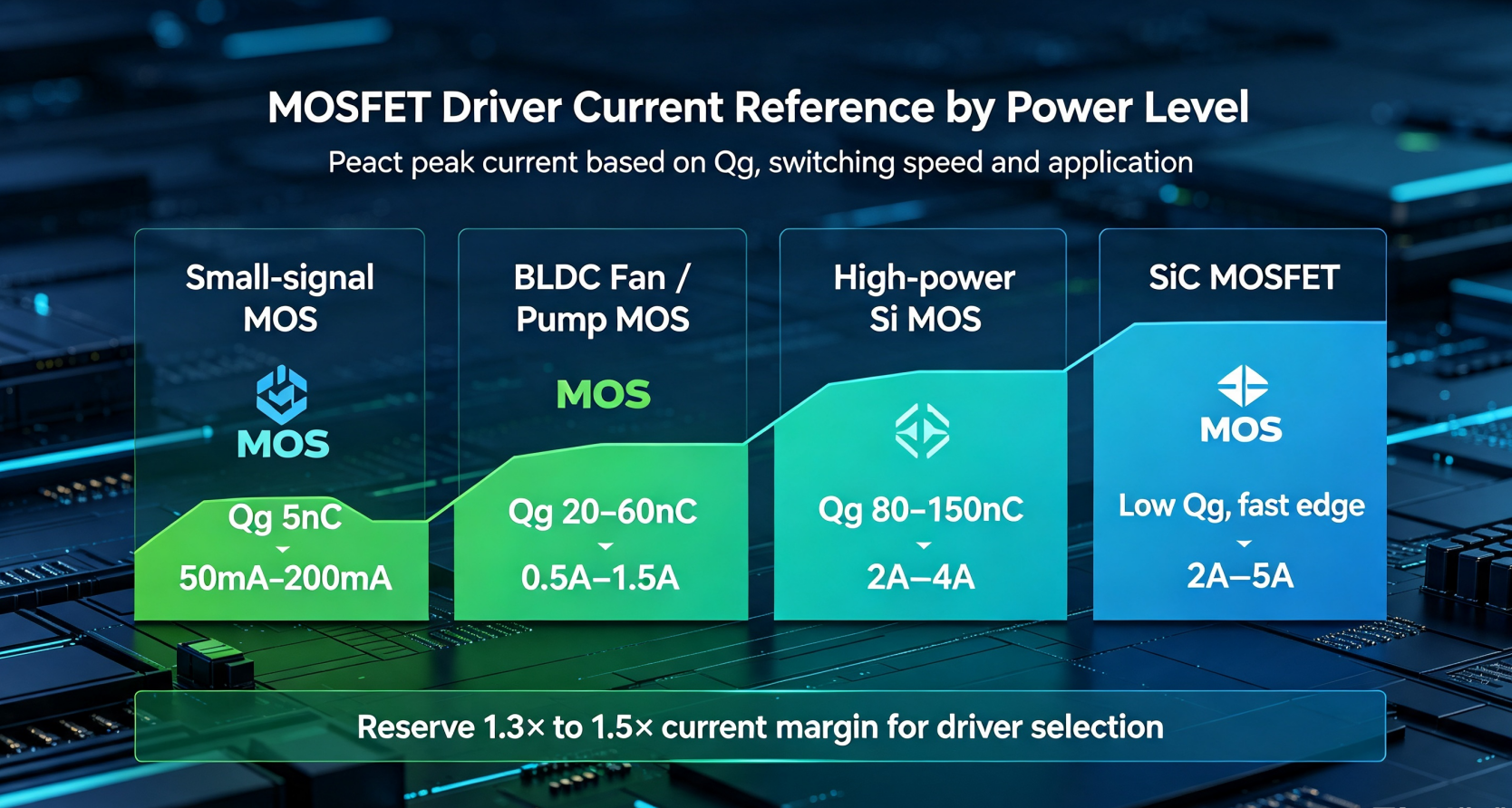
Small-signal MOSFET (AO3400, 2N7002, low-load switching)
Recommended peak driving current: 50mA ~ 200mA
Applications: Signal switching, low-current load switches
⚠️ Direct driving via MCU GPIO works in some scenarios, but a push-pull buffer is still recommended for high-frequency operation.
Medium & small-power SMD power MOSFET (Widely used in BLDC fan & water pump controllers)
Recommended peak driving current: 0.5A ~ 1.5A
Most consumer BLDC pre-driver ICs offer 0.6A ~ 1.2A peak driving capability.
High-power silicon MOSFET (E-bikes, high-power power supplies)
Recommended peak driving current: 2A ~ 4A
SiC MOSFET
Recommended peak driving current: 2A ~ 5A
3. Calculation Example for BLDC Design
Ipeak = 50nC ÷ 50ns = 1A
A safety margin of 1.3~1.5 times should be reserved for engineering design. The driver IC must support at least 1.3A peak current.
4. Two Common Design Pitfalls
-
Source current and sink current are equally critical
Many driver ICs have asymmetric source and sink parameters. Insufficient sink capacity easily causes Miller-induced false turn-on, leading to shoot-through and permanent damage of upper/lower bridge MOSFETs.
-
Higher driving current does not equal better performance
Excessive driving current creates ultra-fast switching edges and high dv/dt, resulting in severe gate oscillation, EMI noise and voltage spikes.
Solution: Add a gate resistor (Rg) to limit peak current, balancing power loss and EMC performance.
5. Summary for BLDC Brushless Motor Design
- Medium & low-power solutions: Select pre-driver ICs with 0.6A ~ 1.2A peak driving capability
- High-speed high-power motors: Adopt drivers with peak current above 2A
6. Quick Selection Rule
Select driver IC with 1.3~1.5 times current margin;
Match proper gate resistance to balance heat, EMI and switching speed.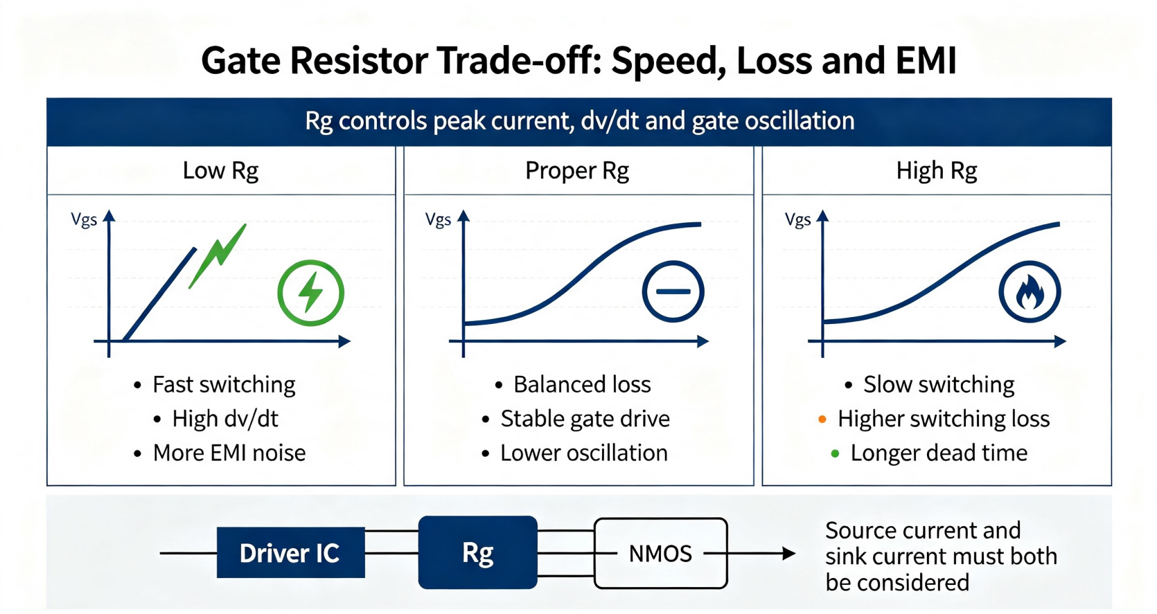


-

Differences Between Depletion-Mode MOSFETs and ...
-
The three main roles of MOSFETs
-

How to Choose MOSFETs for High-Frequency BLDC F...
-

How to Select Gate Resistor for Anti-Reverse MO...
-

High Voltage Gate Drivers: Advancing Power Elec...
-

Differences Between IGBT and MOSFET
-

Power MOSFET Avalanche Guidelines: Ensuring Rel...
-

Basic Understanding of MOSFET
-

EV dashboards are prone to break down, maybe it...
-
Large Package MOSFET Design Knowledge
-

Unleashing the Power of MOSFETs and Transistors...
-

How to Measure MOSFET Power Breakdown: A Compre...
-

High Side and Low Side Drivers: Powering Modern...
-

Understanding MOSFET Overdrive Voltage: Compreh...
-

Determining MOSFET Threshold Voltage: Expert Te...
-

Understanding MOSFET Soft Switching: A Comprehe...


