
- How to distinguish between P-channel and N-channel MOSFETs
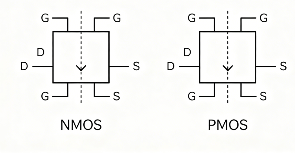
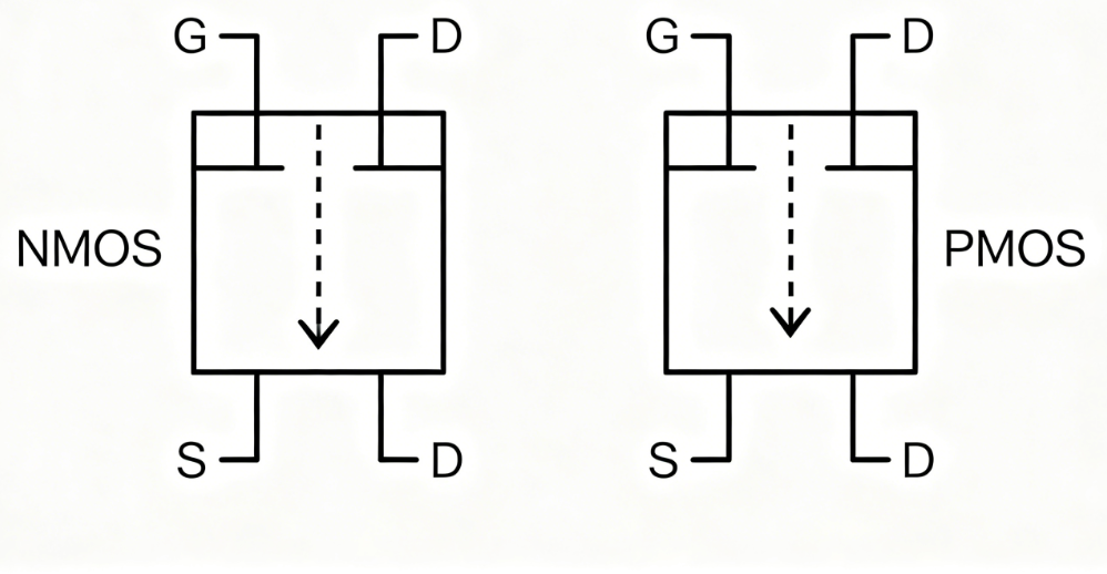
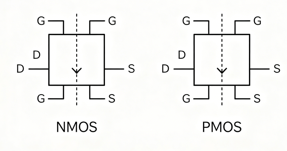
- 1. Check circuit symbols/schematic diagrams (Quick static identification)Focus on the substrate arrow of the MOSFET symbol:
- N-channel MOSFET (NMOS): The arrow points inward toward the device body/gate.
- P-channel MOSFET (PMOS): The arrow points outward away from the device body.
- This rule applies to both enhancement-mode and depletion-mode MOSFETs, as well as silkscreen symbols on PCBs.
- 2. Test with a multimeter (Diode mode, for bare devices)All MOSFETs contain an inherent body diode between Drain (D) and Source (S).
- Use the diode/beep mode of a digital multimeter (the red probe connects to the internal positive pole, and the black probe to the negative pole). Ignore the Gate (G), which is normally non-conductive.
- NMOS: Conducts when the red probe touches Drain (D) and the black probe touches Source (S); blocks in reverse.
- PMOS: Conducts when the red probe touches Source (S) and the black probe touches Drain (D); blocks in reverse.
- Note: If the Gate conducts with D/S in either direction, the MOSFET is damaged.
- 3. Live circuit testing (For soldered devices on PCBs)Conduction voltage logic
- Enhancement NMOS: Turns on when gate voltage (\(V_G\)) is higher than source voltage (\(V_S\)); turns off when \(V_G \le V_S\). Mostly used as low-side switches (connected to GND).
- Enhancement PMOS: Turns on when gate voltage (\(V_G\)) is lower than source voltage (\(V_S\)); turns off when \(V_G \ge V_S\). Mostly used as high-side switches (connected to VCC).
- Quick judgment by circuit position
- MOSFET between load and GND: Generally N-channel.
- MOSFET between load and VCC: Generally P-channel.
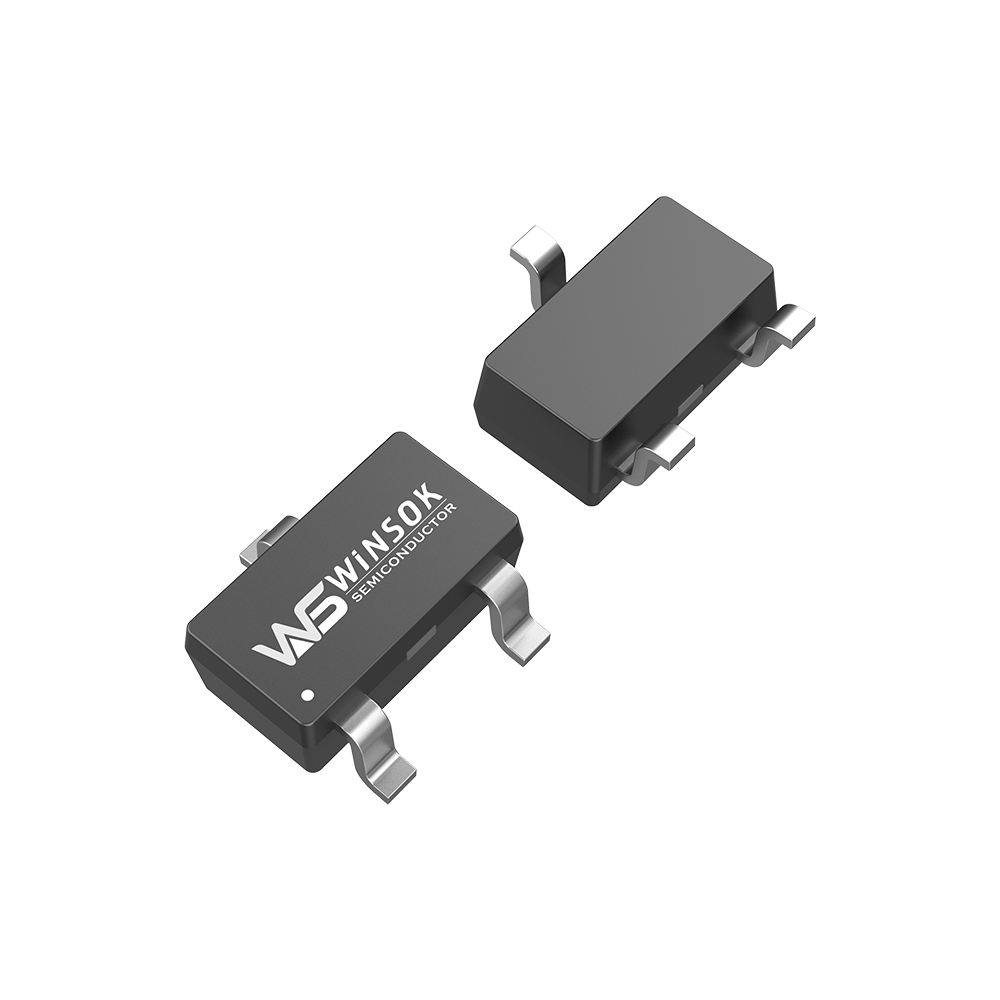
- 4. Check package markings and pin definitions
- Some manufacturers directly mark N / P / NMOS / PMOS on the device surface, especially for high-power MOSFETs.
- Refer to the datasheet: Pin diagrams and internal schematics clearly indicate N-channel or P-channel.
- 5. Auxiliary identification for depletion-mode MOSFETs
- N-channel depletion MOSFET: Conducts naturally at \(V_{GS}=0\), and works with positive, zero or negative \(V_{GS}\).
- P-channel depletion MOSFET: Conducts naturally at \(V_{GS}=0\), and works with negative, zero or positive \(V_{GS}\).
- The body diode test method is still valid for distinguishing channel types.6. Special cases: Paired MOSFETs & integrated dual MOSFETs
- Dual MOSFET packages usually integrate complementary N-channel + P-channel pairs; refer to datasheet pinout for confirmation.
- Load switches and analog switches typically use NMOS for low-side circuits and PMOS for high-side power circuits.
- Priority of identification methods (by convenience)
- Check the arrow on circuit symbols
- Measure the body diode with a multimeter (for bare MOSFETs)
- Judge by mounting position on the PCB
- Test gate-source voltage and conduction logic under power
- Verify via device silkscreen and official datasheet


-

Analysis of the reasons for the ineffectiveness...
-

Briefly talk about the production method of a h...
-

MOSFET Failure Analysis: Understanding, Prevent...
-

Understanding Cascode Amplifier MOSFETs: The Ul...
-

Understanding MOSFET Switching Speed for Optima...
-

MOSFET Gate, Drain, and Source: Core Principles...
-

De rol van vermogens-MOSFET-apparaten
-
What are the causes of heat in the MOSFET of an...
-

MOSFET Replacement Principles
-

2N7002 LTspice Modeling and Simulation Guide
-
Why is it always difficult to test high power M...
-

Advantages of MOSFETs in Motor Drive Applications
-

Why are MOSFETs voltage controlled?
-

Ideas to solve the serious heat generation of M...
-
Olukey: Let’s talk about the role of MOSFET in ...
-
MOSFETs in Electric Vehicle Controllers


