


1. Basic Definition
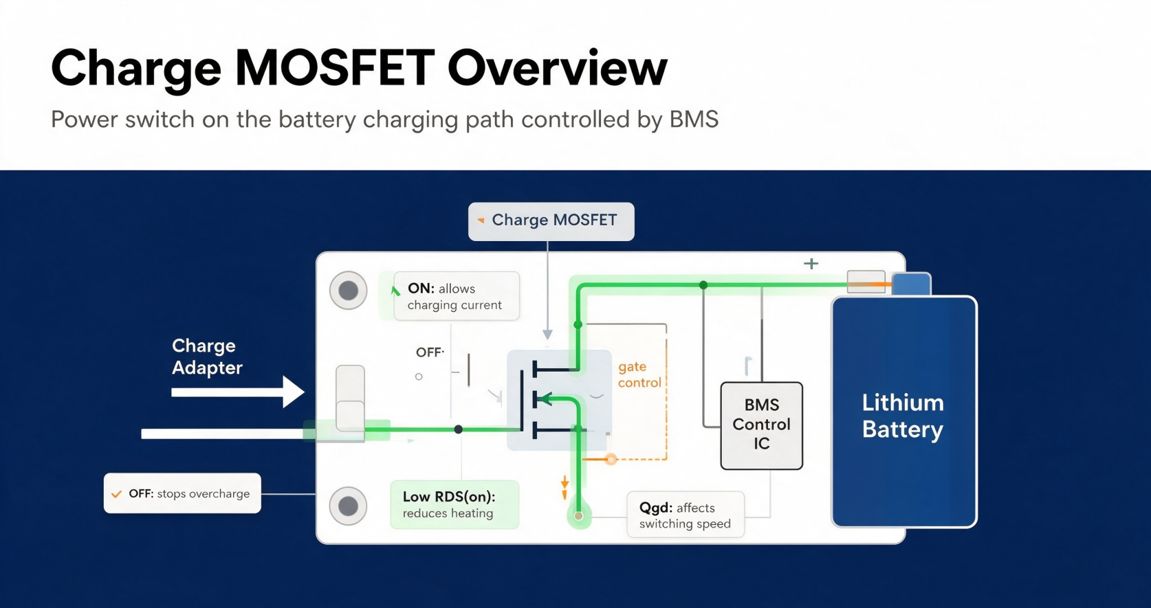
Charge MOSFET is not a dedicated special type of MOS device. It is a universal industry term referring to the power MOSFET placed on the battery charging circuit path. Controlled by BMS or charging management IC, it governs charging voltage, current and all safety protection actions.
This component is widely deployed in lithium battery protection boards, power banks, laptop internal batteries, electric tool battery packs and energy storage charging systems.
There are two mainstream circuit layouts for charge MOS:
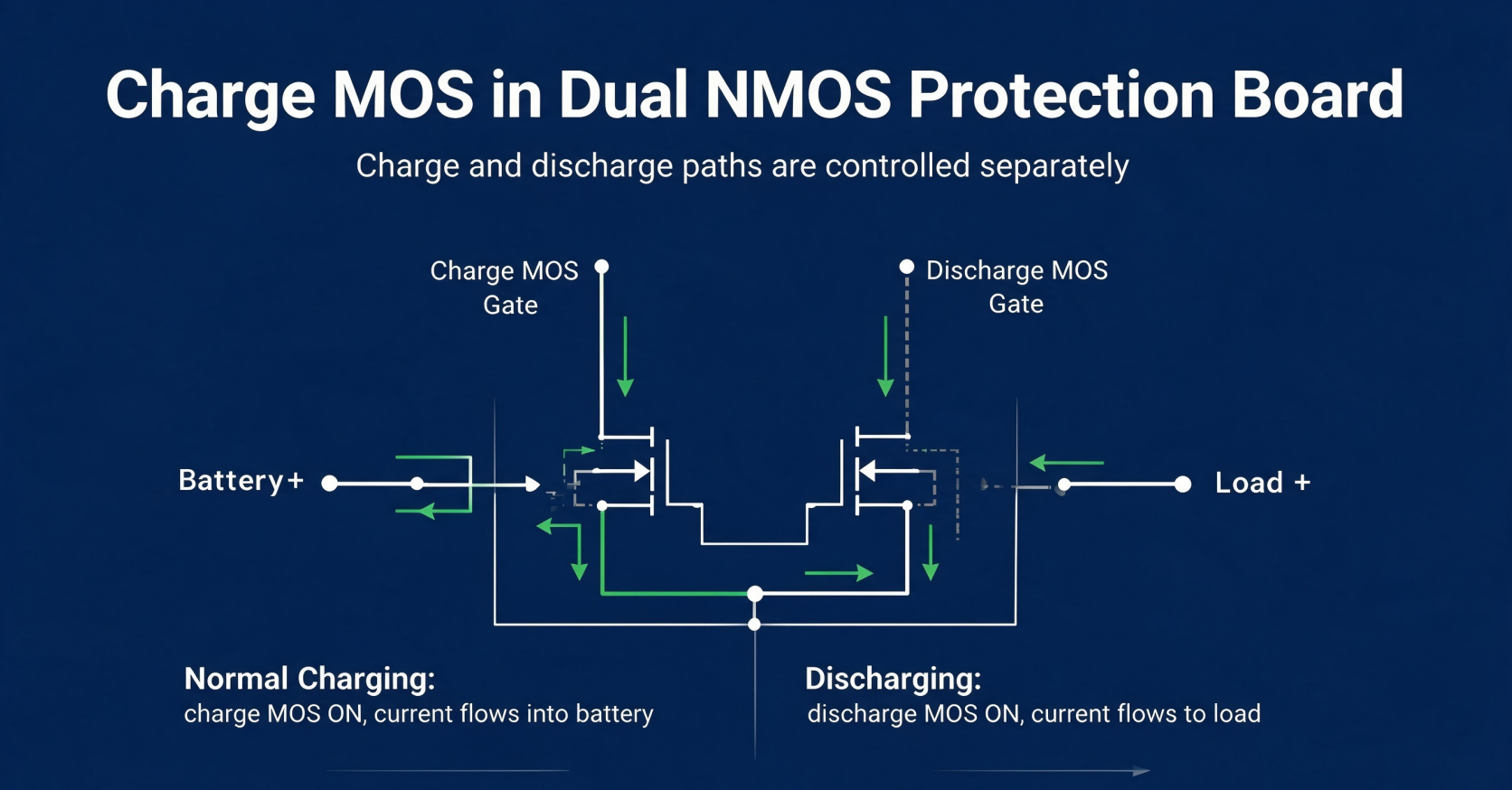
The first solution is the back-to-back source-to-source dual NMOS structure commonly seen on battery protection PCM. One MOS serves as charge MOS to manage incoming charging current, while the other acts as discharge MOS to control outgoing load current. The two devices work independently to achieve full bidirectional voltage blocking.
The second layout uses a high-side PMOS on the adapter-to-battery input loop. This PMOS functions as a charge switch to realize reverse insertion protection and charging enable/disable control.
2. Core Functions of Charge MOSFET
Switch Control for Charging Loop
The charging IC outputs gate drive voltage to turn on the charge MOS, allowing current to flow into the lithium cell. When the battery reaches full rated voltage, the IC pulls down the gate signal to shut off the MOS entirely. This physical disconnection stops overcharging, which would otherwise trigger battery bulging or thermal runaway hazards.
Charging Current Limitation
The control IC adjusts gate-source voltage to operate the charge MOS within its ohmic region. The device acts like an adjustable resistor to cap charging current at a safe preset level. This suppresses excessive charging current and prevents lithium dendrite growth inside battery cells.
Instant Fault Protection
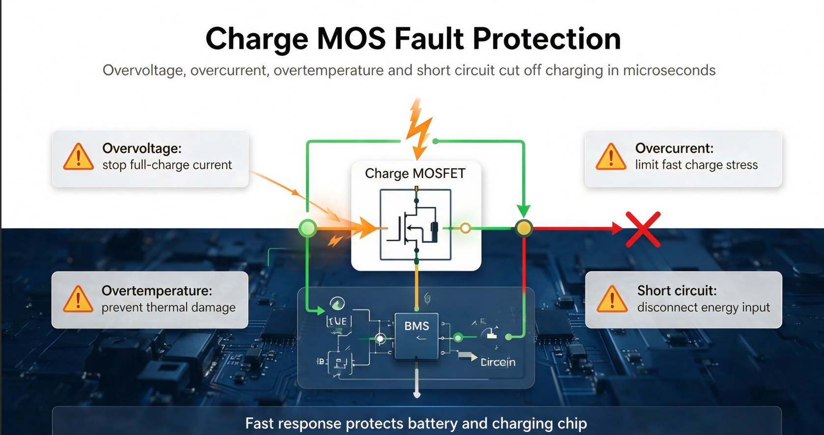
Once the BMS detects abnormal conditions including overvoltage, overcurrent, overheating or short circuit, the charge MOS will switch off within microseconds to cut off energy input. It stops charging under high temperature to avoid thermal damage, isolates power instantly during short-circuit incidents to eliminate fire risks, and blocks reverse current to protect the charging chip from reverse plug damage.
Low Power Loss Conduction
Charge MOSFETs feature ultra-low milliohm level on-resistance. Minimal conduction resistance cuts heat generation during high-current fast charging, reducing thermal design pressure for adapters and battery packs.
3. Operating Principle of Dual NMOS Battery Protection Board
Under normal charging conditions, the gate of charge MOS receives high driving voltage and the channel turns on. Charging current flows through the charge MOS channel into the battery, while the discharge MOS stays off with only tiny leakage current passing through its body diode.
When the battery is fully charged or enters an overvoltage state, the BMS IC detects cell voltage exceeding the safety threshold and pulls the charge MOS gate to low potential. The MOS channel closes completely, and no more current can flow into the battery cell.
During battery discharge, the charge MOS remains turned off. Only the discharge MOS opens to supply power to external loads, and the charge MOS only relies on its body diode to block reverse voltage without bearing discharge current.
4. Key Selection Parameters for Charge MOSFET
First, low Rds(on) is essential to reduce conduction loss for high-current fast charging scenarios. Second, the continuous drain current rating must fully match the peak charging current of the equipment. Third, drain-source breakdown voltage needs enough margin based on battery series count. Fourth, low total gate charge ensures fast switching response for rapid fault protection. Fifth, optimized body diode reverse recovery characteristic reduces extra heat during transient current changes.
5. Main Application Scenarios
Single-cell lithium protection circuits for power banks, wireless earbuds and smart watches; multi-cell battery packs for electric drills, electric bicycles and notebook built-in batteries; PD/QC fast charging adapter main circuits; industrial energy storage and UPS battery management systems.
6. Distinction Between Charge MOS and Discharge MOS
The charge MOS is responsible for cutting off incoming charging current to prevent overcharging, and only bears current flowing into the battery during charging. Its core protection missions cover overcharge, charging overcurrent and reverse adapter insertion, and it keeps off when the battery supplies power to loads.
The discharge MOS focuses on cutting off outgoing load current to avoid overdischarging. It only carries current flowing out of the battery during discharge, and handles protection against overdischarge, load short circuit and discharge overcurrent. This MOS stays off while the battery is being charged.


-

What are the main features of MOSFETs?
-

Working with MOSFETs: Essential Knowledge for E...
-

Building the Perfect Ideal Diode with MOSFETs: ...
-

About MOSFET driver
-

MOSFET Gate, Drain, and Source: Core Principles...
-

How to Select Gate Resistor for Anti-Reverse MO...
-

Technology Trends in the MOSFET Market – with W...
-

Wiring a MOSFET for Your Nerf Blaster: Professi...
-
What are the causes of inverter MOSFET heating?
-

Understanding MOSFET Overdrive Voltage: Compreh...
-

MOSFET Key Characteristics
-

Differences Between Depletion-Mode MOSFETs and ...
-

Do you know the MOSFET driver circuit?
-

MOSFET Selection | N-Channel MOSFET Constructio...
-

Understanding CMOS Switch Technology: From Basi...
-

What can I do to fix my MOSFET that is heating ...


